
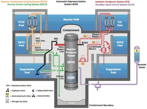
The primary function of the Isolation Condenser System is to remove excess decay heat to prevent the activation of the Emergency Core Cooling System. By removing this decay heat, the reactor pressure remains below the setpoints of the Automatic Depressurization System an. The Isolation Condenser System prevents the depressurization and thus a loss of coolant volume which would require additional procedures to restart the reactor. The system consists of four separate isolation condensers which are located at a higher elevation than the reactor pressure vessel. The isolations condensers transfer heat from the steam produced reactor to the atmosphere via heat exchanger tubes that are located in the isolation condenser cooling pool. (GE Hitachi, 2011, June 1, p. 44-45).
The Isolation Condenser System is made up of three main parts the steam side, the condenser pool, and the condensate side. As shown in Figure 1, piping from the reactor pressure vessel leads into the steam side of the isolation condenser. Steam from the reactor pressure vessel travels through these pipes into the condenser upper header where it is cooled and condensed by the condenser pool. Steam flows from the upper header through the tubes of heat exchanger where it is condensed back into water and collects in the lower header of the heat exchanger. The condensate returns through the condensate return line and builds up in an inline condensate vessel. The inline condensate vessel must remain filled in anticipation of the initiation of the Isolation Condenser System. To keep the inline condensate vessel full, the condensate return isolation valve and the bypass valve leading to the reactor pressure vessel is kept shut during normal reactor operation. The steam side of the system is kept open during normal reactor operation. This valve configuration allows steam from the reactor to continuously condense in the isolation condenser to fill up and maintain a volume in the inline condensate vessel. (GE Hitachi, 2011, June 1, p. 45)
When the system is initiated when the condensate return isolation valve or bypass valve is opened. This allows the initial condensate to drain from the inline condensate vessel into the reactor pressure vessel. The condensate continues to flow from the isolation condenser to continue to fill the condensate return line. Steam from the reactor pressure vessel flows up through the vertical pipes and into the horizontal headers. “Each pipe is provided with a built-in flow limiter, sized to allow natural circulation operation of the isolation condenser at its maximum heat transfer capacity” (GE Hitachi, 2011, June 1, p. 45). Steam condenses in the vertical tubes which are cooled by the isolation condenser pool, the condensate is collected in the lower horizontal header. The condensate flows from the header through the condensate return line the inline condensate vessel into the reactor pressure vessel, thus cooling it down.

- Isolation Condenser System (Standby Mode) (GE Hitachi, 2011, June 1, p. 45)
There are two parallel valves, shown in Figure 1, that connect the isolation condenser condensate return piping to the reactor pressure vessel. The condensate return valve and the condensate return bypass valve are what separate the condensate return from the reactor. If the system is activated manually, then the condensate return valve will be opened remotely. If the the system is activated because of reactor system failures, then the condensate return bypass valve will fail open. (GE Hitachi, 2011, June 1, p. 46)
The isolation condenser expansion pool is equipped with both water level and radiation monitoring equipment. Water level monitoring instruments, located inside of the pool will produce an alarm signal, which indicates inside the main control room, when the water level is high or low. The radiation monitor is located in atmospheric area above the isolation condenser pool. This monitor will produce an alarm signal, which indicates inside of the main control room, when radiation is detected in the pool. This indicates that there is a leak in the isolation condenser piping allowing water from the reactor to exit containment. (GE Hitachi, 2011, June 1, p. 46 & 2007, p. 307).
The Gravity Driven Core Cooling System is in place to significantly cool the reactor core and provide makeup water if a loss of coolant accident were to occur. The system consists of four separate and identical trains which are located at a higher elevation than their inlet to the reactor pressure vessel. Three subsystems make up the Gravity Driven Core Cooling System; the short term cooling system, long term cooling system and the deluge line system. For a loss of coolant accident, gravity driven cooling water to the reactor is supplied through the short-term and long-term systems. For a core meltdown, gravity driven cooling water to the drywell is supplied through the deluge lines. (GE Hitachi, 2011, June 1, p.47-48)

The short-term and long-term cooling systems, as shown in Figure 2, are made up of made up of a pool, a check valve and a squib valve. The short-term system connects from the gravity driven cooling system pool to the reactor pressure vessel. The long-term system connects from the suppression pool to the reactor pressure vessel. The deluge line connects from the gravity driven cooling system pool and drains directly into the dry-well through three squib valves. All of the squib valves are normally closed. Once opened via the ignition of an explosive charge, the valve will remain open to allow constant flow from the gravity driven cooling system pool to the lower drywell.
The Gravity driven Cooling System can be manually initiated by the operator in the main control room. The operator can blow open the squib valves to allow the flow only after the interlock criteria has been satisfied. The interlock requires that the reactor pressure vessel has been depressurized so that the water from the pool can flow with only the pressure head from gravity.
Automatic initiation of the short-term system occurs when the reactor water level reaches level 1 and the reactor has been depressurized by the Automatic Depressurization System. This interlock with the Automatic Depressurization System ensure that the pressure is low enough for the water to gravity flow into the reactor pressure vessel. The injection line squib valve is opened to allow cool water to be injected into the reactor pressure vessel. The long term system is initiated automatically after the short term has already been activated, the reactor water level reaches level 0.5, and the time delay has passed. The equalization line squib valves are opened to allow for water to continuously flow from the suppression pool into the reactor pressure vessel.
Special high temperature thermocouples, located below the basemat material in the drywell, are used to activate the deluge system when a high basemat temperature signal is detected. The deluge squib valves are opened to allow cool water to flush to the floor of the drywell to cool a molten core. (GE Hitachi, 2007, September 4, p. 205-206 & 2011, June 1, p.48).
The gravity driven cooling system pool and the suppression pool is equipped with water level monitoring equipment. Alarms in the main control room exist for both high and low level. Water level for the gravity driven cooling system pools, suppression pools and reactor pressure vessel are indicated in the main control room. Drywell and reactor pressure vessel pressure indications are used for initiation of the cooling system. The reactor must be depressurized prior to initiating the Gravity Driven Cooling System. Drywell temperature is monitored by a thermocouple to initiate the deluge valves. The check and squib valves both have position indication. The squib valves have an alarm for when they are opened. (GE Hitachi, 2007, September 4, p. 216).
The Automatic Depressurization System acts to depressurize the reactor pressure vessel by relieving pressure to allow for the initiation of the Gravity Driven Cooling System water injection. Shown in Figure 3, the system is made up of ten safety relief valves which are connected to the main steam lines and eight depressurization valves which are connected to the reactor pressure vessel via stub lines. The system can be automatically initiated in either of the two situations: ten seconds of a low water level in the reactor pressure vessel or one hour of high pressure in the drywell. (GE Hitachi, 2011, June 1, p. 51-52).

The safety relief valves are initiated in separate groups to allow for the drop in pressure in the reactor pressure vessel as well as the temperature in the suppression pool to settle before the next set is opened. When the pressure drops inside of the reactor pressure vessel, the water will flash to steam and boil vigorously, thus causing the water level to swell. If the level swells too high it will push water through the steam dryers and allow the water to escape out of the safety relief valves resulting in a loss of water volume from the reactor pressure vessel. The suppression pool needs a little bit of time to condense the steam from the safety relief valves. The first set of five valves will open when the water level reaches level 1. The second set of five valves is time delayed after the first set. As shown in Figure 4, every safety relief valve relieves pressure into the suppression pool through a line, equipped with two vacuum breakers, that discharges below the surface of the pool. (GE Hitachi, 2011, June 1, p. 43, 51).
The depressurization squib valves are blow open in separate groups after all of the safety relief valves have been opened. The depressurization valves are also grouped and time delayed to open after the safety relief valves to also minimize the swell inside the reactor which could cause a loss of water volume from the reactor pressure vessel. The depressurization valves relieve pressure into the drywell as shown in Figure 4. All of the squib valves are normally closed. Once opened via the ignition of an explosive charge, the valves will remain open to allow a constant flow of steam from the reactor pressure vessel to the lower drywell. The depressurization valves allow two times as much steam to flow through as compared to the safety relief valves, thus quickly depressurizing the reactor pressure vessel. (GE Hitachi, 2011, June 1, p. 43, 51)
The Standby Liquid Control System is a backup Emergency Core Cooling System that serves two purposes, to shut down a full-powered reactor and to maintain it at a subcritical level, also to provide additional coolant in the event of a loss of coolant accident. As shown in Figure 5, the system is made up of two trains to provide redundancy in the system. Each of the accumulators contain enough water to fill half of the reactor pressure vessel (GE Hitachi, 2011, June 1, p. 54).
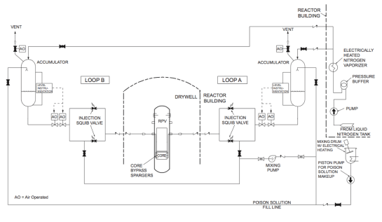
Following the schematic in Figure 5, the Standby Liquid Control System is made up an accumulator that is full of a boron solution call sodium pentaborate. The accumulator is pressurized by nitrogen and held under pressure during normal operations, ready to inject the solution into the reactor pressure vessel. From the accumulator, the fluid travels through two injection line shut off valve that are normally open and then through two injection squib valves that are opened when the system is initiated. After the squib valves the fluid flows through two check valves and enters into the bypass region of the reactor pressure vessel where it flows directly into the core.
The sodium pentaborate solution is considered a neutron poison, which means that it absorbs the thermal neutrons that are created during the nuclear fission reaction. According to GE Hitachi, “At all times when it is possible to make to the reactor critical, the Standby Liquid Control System will be able to deliver enough sodium pentaborate solution into the reactor to assure reactor shutdown” (2011, June 1, p. 55). After activation, when the solution level inside of the accumulator drops down to a low level point, the level instrumentation triggers the logic to shut the two injection line shut-off valves to prevent the pressurizing nitrogen from entering into the reactor pressure vessel. Also, when the shut-off valves are shut, the accumulator vent is opened to further ensure that the nitrogen is not pushed into the reactor pressure vessel.
Instrumentation and control is used to monitor the system’s readiness and to ensure its operation. Valve position indicators in the main control room are used with the squib valves and the shut-off valves. The level in each accumulator is measured by four redundant level monitors. Pressure of each accumulator is measured by two redundant pressure monitors. The level and pressure are displayed locally as well as in the main control room. Alarms for both level and pressure are at high, low and low-low setpoints. (GE Hitachi, 2007, ch. 7 p. 260 & ch.9 p. 128)
The Standby Liquid Control System can be activated both manually and automatically. To operate the system manually, the operator in the main control room activates the explosive charges on the squib valves to allow the flow of the boron solution to the reactor. Manual activation is only done upon failure of the control rods when it is determined that the reactor can not be kept shutdown and subcritical. Automatic activation occurs within the Emergency Core Cooling System when a loss of coolant event occurs or during an anticipated transient without scram, where the signals endure for longer than allowed. (GE Hitachi, 2007, ch.9 p. 124)
The Emergency Core Cooling System is activated during unsafe reactor conditions and uses its subsystems to bring the reactor into a safe and under control condition. Together, the subsystems form a diverse, effective, and redundant set of controls measure for equipment failures, uncontrolled transients, and reactor accidents.
The primary function of the Isolation Condenser System is to prevent the activation of the Emergency Core Cooling System. Isolation condensers remove heat and reduce pressure to avoid the need for the Automatic Depressurization System. The Automatic Depressurization System is the first system to initiate when emergency core cooling is needed. The depressurization is necessary to allow for the gravity driven core cooling to flow into the reactor pressure vessel at atmospheric pressure.
The Gravity Driven Core Cooling System is the key component to significantly and continuously cool down the reactor once activated. It also operates the deluge system which is essential to cool the core if it were to melt through the vessel into the drywell. The Standby Liquid Control System is also activated after the Automatic Depressurization System and provides additional water volume to the Emergency Core Cooling System for a loss of coolant accident. It also works on its own to shutshutdown the reactor in the event that the control rods cannot do so.
The development of this Emergency Core Cooling System has come from many years of lessons learned and a history of making safe and reliable reactors. GE Hitachi has made significant efforts to make this reactor system as safe as possible with the latest technology.
References
GE Hitachi Nuclear Energy. (2011, June 1). ESBWR Plant General Description [PDF File] Retrieved from https://nuclear.gepower.com/content/dam/gepower-nuclear/global/en_US /documents/ESBWR_General%20Description%20Book.pdf
GE Hitachi Nuclear Energy. (2011). ESBWR Passive Safety Fact Sheet [PDF File] Retrieved from https://nuclear.gepower.com/content/dam/gepower-nuclear/global/en_US /documents/product-fact-sheets/ESBWR%20Passive%20Safety%20Fact%20Sheet.pdf
GE Hitachi Nuclear Energy. (2007, September). 26A6642AW, Rev. 4, ESBWR Design Control Document, Tier 2, Chapter 7, Instrumentation and Control Systems. From https://www.nrc.gov/docs/ML0729/ML072900648.pdf
GE Hitachi Nuclear Energy. (2007, September). 26A6642AY, Rev. 4, ESBWR Design Control Document, Tier 2, Chapter 9, Auxiliary System. From https://www.nrc.gov/docs/ML0729/ML072910044.pdf

Leave a comment